


Tech Info
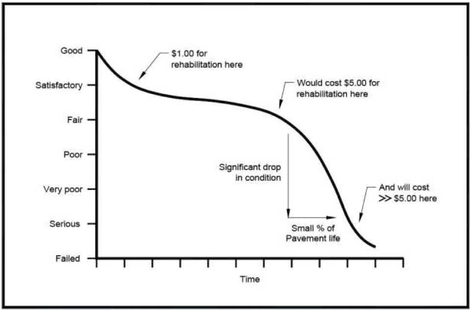
Roadways play a critical role in the competitive infrastructure at every level of government. As noted in figure below, the Life Cycle of PCC pavement is such that timely rehabilitation is critical to assure high-quality roadways without incurring significant costs over the long run.
Rehabilitation of existing pavements ranks among the most significant priorities facing local, regional, and national transportation authorities. The use of hot-mix asphalt (HMA) overlays provides a long-term and economical solution to the pavement rehabilitation challenge and has done so for decades. HMA overlays increase the structural capacity of existing pavement systems and improve the long-term functional pavement performance, improving ride, noise reduction and aesthetic appearance.
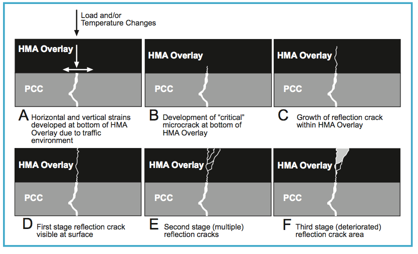
Historically, the biggest impediment to effective HMA overlay on PCC pavement has been reflective cracking over time in the HMA overlay. The figure below outlines the typical cycle of reflective cracking when asphalt is directly overlayed on a PCC pavement (without resonant rubblization).
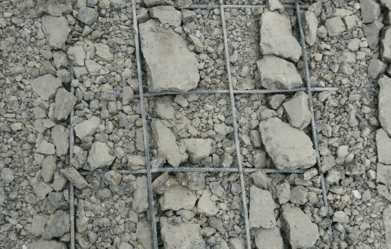
The best method to eliminate reflection cracking in an HMA overlay over a PCC pavement is to fracture the slabs before placement of the HMA overlay. “Slab fracturing” techniques have proven to be an excellent method for preparation of the PCC pavement priory to overlay with HMA. Resonant rubblization has been used around the world used to eliminate reflective cracking in HMA overlays on PCC. This process is achieved by fracturing the slab into interlocking fragmented pieces, resulting in destruction of the existing slab action of the PCC pavement. With resonant technology from Quasco, our fracturing process is highlighted as follows:
Reinforcing steel bar, if present in the PCC pavement, is fully debonded from the concrete with resonant rubblizing. The rubblization process is applicable to all types of PCC pavements.
Resonant rubblizing has proven to be the most economical and successful ways to eliminate reflection cracking. The reduction of the effective slab length results in minimal horizontal movements at joints and cracks due to temperature and moisture changes. This greatly minimizes the tensile and shear forces normally occurring at the bottom of the HMA overlay.
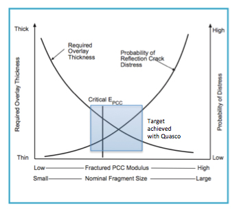
The graphic below shows the relationship of the rubblized slab modulus (EPCC) to both functional distress caused by reflection cracking and structural requirements of the HMA overlay. As the rubblized PCC modulus decreases (slab becomes more intensely fractured), the likelihood of having reflection cracking problems in the HMA overlay is significantly reduced. However, as the fractured PCC modulus decreases, the structural capacity of the fractured PCC slabs also decreases, requiring a thicker HMA overlay. The ultimate goal is to reduce the EPCC value to a minimum or critical value such that reflection cracking will not occur, but not so low a value that the capacity of the fractured slab is reduced to a point where an excessive HMA overlay thickness is required. Resonant rubblization achieves the target range of rubble noted in the graph below.
Studies have consistently shown the rubblized roads with an asphalt overlay have an average useful life of over 20 years, while costing 50% less than the cost of tear out and replacement of while requiring only ≈ 20% the down time. Our rubblizing machines average approximately 7,000 square meters per workday.
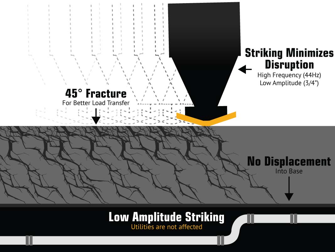
After the PCC has been rubblized, heavy traffic loading will not cause slab reflection provided the concrete is fractured with resonant technology which retains the highest modulus, best structural coefficient, and the ability to distribute surface loading over a wider base. Achieving all of this requires that the concrete be fractured on the shear plane, i.e., at a 45-degree angle. This pattern provides for a greater modulus compared to a vertical fracturing pattern. The method distributes the traffic load over a greater area and leads to a greater modulus than may be achieved by other fracturing methods.
The structural coefficient of a crushed stone base is typically .14, a stabilized base is .25, and that of a resonant rubblized slab on a substantial base material ranges from .25 to .28. Slabs supported only by sand or unconsolidated base material will produce a structural coefficient of from .16 to .25. Rubblized pavements tested with the Falling Weight Deflectometer (FWD) method have shown that the inherent strength of the rubblized layer is between 150% and 300% of the effective in load distribution compared to a high quality dense graded crushed stone base.
The strength of the rubblized PCC (as measured by the FWD) has been subsequently site tested and has improved year over year. These ever improving deflection measurements are a result of the smaller particles produced by resonsant rubblization near the surface of the PCC are continuously driven deeper into the fracture lines by the traffic and resulting vibration.
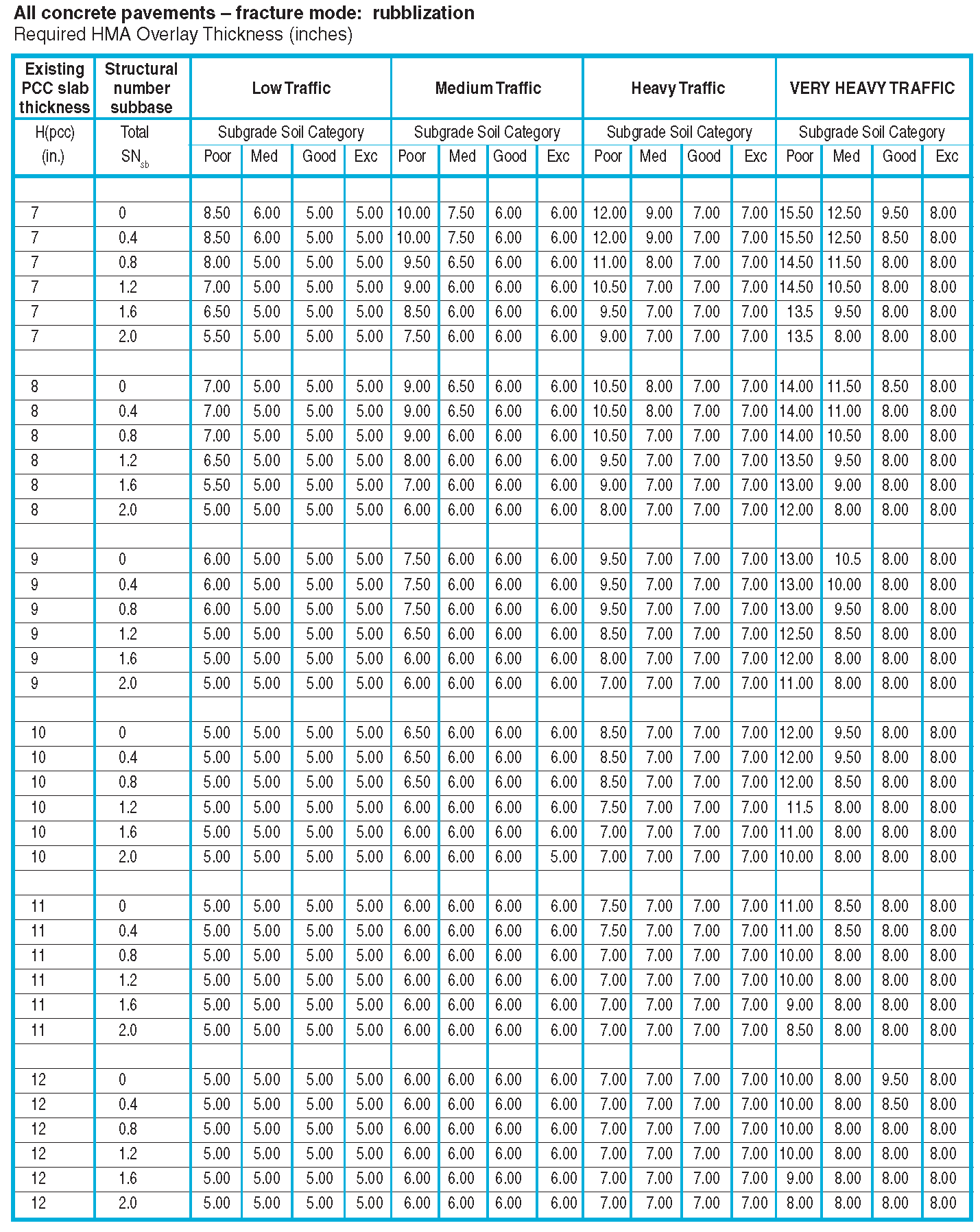
Of course, the question always is, “how much asphalt overall do I need if I use resonant rubblization for my rehabilitation project?” Our answer always is….well, it depends (on a lot of factors).
However, we find this chart a good guide to be used as a starting point (from Rubblization Design and Construction Guidelines on Rubblizing and Overlaying PCC Pavements with Hot-Mix Asphalt – National Asphalt Pavement Association ) considered a Level 1 analysis:
For a more in-depth approach, see this Level 2 Analysis that is an enhanced engineering analysis for more complex jobs requiring more inputs.
Drainage
Water intrusion into pavement structures has been a source of reduced service life since the earliest roads were constructed. The holds true for roadways rehabilitated with resonant technology. It is important to install edge drains as a part of the rehabilitation process. The principles of drainage management for pavement structures have not changed radically since AASHTO published the 1986 Guide for Design of Pavement Structures.
Positive drainage measures are defined as permeable bases and the water gathering and discharge system required for these bases. They are generally synonymous with internal or subsurface pavement drainage (under-drain) features.
Edge drains are designed in a wide variety of ways, but are generally between 18- and 24-inches deep, 12-inches wide, and are lined with a felt or other types of fabric filter. Laid in the bottom of the trench is either a 4-inch perforated PVC pipe or a geo-tech covered pipe which is covered with aggregate or pea gravel. Approximately every one to three hundred yards are lateral lines to drain the collected water from the roadway.
The difference in potential of an edge drain compared to an earthen dam allows the water to drain away from under the slab resulting in a dry, firmer base, i.e., a higher modulus. Small vibrations from traffic moving over the road facilitate the movement of the previously trapped water. It is important that the base material not be invaded by broken concrete. Every place the base is invaded is a potential water trap that will not easily drain to the edge drain system. This is achieved with resonant rubblization, while it is not with other methods.
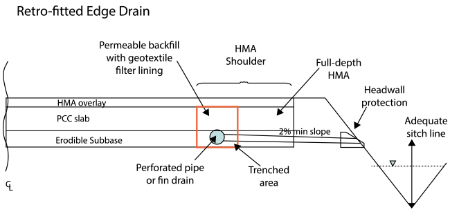
The top 2 to 3 inches of the rubblized slab drains. Properly designed edge drain extends to the drainable layer so water may exit from the roadway. The bottom 6- to 8-inches of the rubblized section is impervious to water that may come from above. The never gets to the base or sub-grade with resonant rubblization.
A typical retro-fiited edge drain design for a rubblized roadway looks like this:
Additional Resources
In terms of drainage research, we highly recommend the following resources:
- Roadside Channel Design – Texas Department of Transportation
- Drainage Design & Analysis – Federal Highway Administration (US)
- Roadside Channel - California Department of Transportation
- Guidelines for Road Drainage – RoadEx.Org
- Guidance Notes on Road Pavement Drainage Design – Hong Kong
- Design Manual for Roads and Bridges: Volume 4 Geotechnics and Drainage (UK)
- Urban Drainage Design Manual - US Department of Transportation